



STMicroelectronics AEK-POW-BMS63EM Evaluation Board

STMicroelectronics AEK-POW-BMS63EM Evaluation Board is a battery management system (BMS) evaluation board that can handle from one to 31 Li-ion battery nodes. Each battery node manages four to 14 battery cells, with a voltage range of 48V to 64V.
Thanks to the two embedded transceivers, the board can be used as the first node in a BMS daisy chain, connected to a battery pack of six, ten (in configuration A or B, as detailed in UM3185), or 14 cells, and in a dual-access ring BMS chain. The board monitors the state of health (SOH) and state of charge (SoC) of each battery and manages battery balancing via passive discharge, thanks to the software already preloaded on the onboard SPC58NN84E7 microcontroller. The board is equipped with two CAN ports that support the versatile CAN2.0 protocol, enabling integration with multiple systems and efficient component communication.
The evaluation board hosts the following devices: SPC58NN84E7, L9963F, L9963T, LM2902W, and STGAP2GS. The SPC58NN84E7 automotive-grade microcontroller is responsible for calculating the SOH and the SoC of the connected battery pack, based on the measurement provided by the L9963F through the L9963T ISOSPI<>SPI transceiver. The L9963T transceiver, the MCU, and the L9963F communicate via the ISOSPI protocol, which uses differential communication for higher noise immunity. The LM2902W is used to sense the temperature in the battery ecosystem (that is, the temperature in the battery pack) through NTCs. The STGAP2GS keeps the control circuit and power circuit electrically separate (isolated), increasing system safety and robustness.
The STMicroelectronics AEK-POW-BMS63EM provides an elaborate monitoring network to sense the current, voltage, and temperature of each cell. This sensing allows elaborating the SoC of each battery cell and, consequently, the state of charge of all battery packs. The SoC allows assessment of the remaining battery capacity, which corresponds to the remaining driving range.
Features
- Hosts
- L9963F AEC-Q100 qualified automotive multicell battery monitoring and balancing IC
- Two L9963T AEC-Q100 qualified automotive general-purpose SPI-to-isolated SPI bidirectional transceivers
- Two CAN-FD transceivers supporting high-speed applications up to 8Mbps
- SPC58NN84E7 ASIL-D MCU, featuring five cores and a hardware security module for system robustness, safety, and integrity, to perform charge balancing and to compute the state of charge (SoC) and the state of health (SOH)
- Two STGAP2GS isolated gate drivers to isolate the microcontroller from overvoltage or faults, and to allow different battery pack connections by driving the MOSFETs that short-circuit unused cells
- LM2902W low-power quad operational amplifier to sense the battery pack temperature
- Four battery pack connections are possible with six, ten (in configuration A or B), or 14 cells, using the AEK-POW-BMS63EM as the first node
- Voltage monitoring of up to 14 battery cells
- Current sensing of the entire battery node
- With two embedded L9963T ISOSPI transceivers, the board allows configuring two different topologies - daisy chain and dual access ring
- Four configurable GPIOs, pluggable with NTCs for temperature measurement through an external temperature sensor
- Three embedded NTCs to sense the BMS node temperature
- Three additional NTCs are hosted on the battery holder connector
- SPI interface to communicate with the MCU
- Passive balancing
- JTAG module for board firmware debugging/programming
- Debug mode for board testing
- Compact 183mm x 78mm size
- Included in the AutoDevKit ecosystem
Applications
- Advanced powertrain applications
- Hybrid Electric Vehicle (HEV) and Electric Vehicle (EV) motor drives
- Electric power steering
- Active suspension applications
- Anti-lock braking
- Advanced Driving Assistance Systems (ADAS)
Application Block Diagram

Related Products
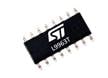
STMicroelectronics L9963T Automotive SPI to Isolated SPI Transceiver
Designed to create a communication bridge between devices located into different voltage domains.
STMicroelectronics SPC58 N Line Performance Microcontrollers
32-bit Power Architecture® microcontrollers for automotive ASIL-D and security applications.
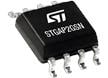
STMicroelectronics STGAP2GSN Isolated 3A Single Gate Driver
This device isolates the gate driving channel, low voltage control, and interface circuitry.
Complete Your Design

STMicroelectronics Standard Products
A broad range of drop-in replacements for general-purpose analog ICs, discretes, and serial EEPROMs.